There are many ways to make railings for a model ship and it depends on how the railings on the real ship have been constructed as to which methods is going to accurately reproduce the look that you require. Railings can be made from photo etched components or they can be built up from wire or plastic or from a combination of materials.
I usually use copper wire or brass soldered together for most of my railings now. To produce the best possible solder joints it is important to make sure that all of the wire is cleaned just prior to soldering and that an appropriate flux is used. A good quality temperature controlled soldering iron with a clean tip will also help to produce better solder joints.
Built up railings generally require some sort of jig to achieve consistent results so most of my railings that I make use a jig. It is not impossible to build railings without a jig but you need a lot more patience than I possess.
The methods that I now use to make built up railings are described below.
Method 1
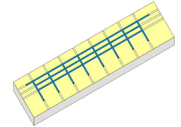
 This type of railing represents tubular stanchions and rails of the same size that are welded together. To make this railing I use a piece of MDF (Craftwood) with grooves filed into the surface as a jig to position the pieces of wire.
I solder the top rail and stanchions together first and then cut pieces of wire to fit between each of the stanchions which are then soldered to make up the center and bottom rails. This method makes up reasonably strong railings but unless you are very skillful at soldering there will be a fair bit of cleaning up to do with a needle file.
Method 2
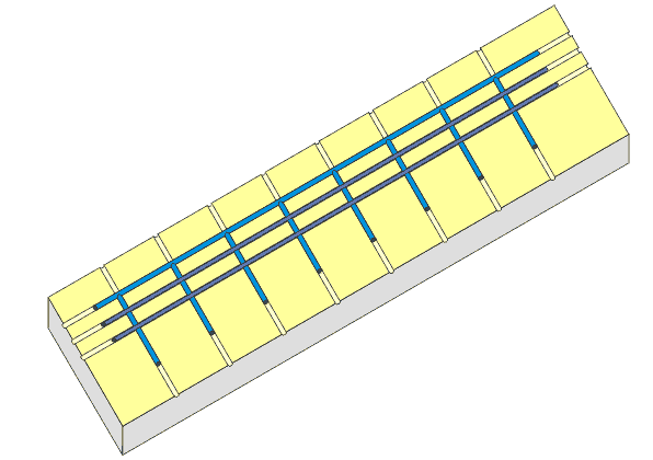
 This method is very similar to the one explained above the difference being that the bottom and center rail are made with smaller diameter wire than the top rail and stanchions.
The same jig can be used and the top rail and stanchions are cut and soldered together as in the method above. I now file about half way through each stanchion with a needle file at each point where the center and bottom rails are to be fitted. A length of smaller diameter wire is then laid in the grooves that have been filed into the stanchions and then each joint is soldered.
Method 3
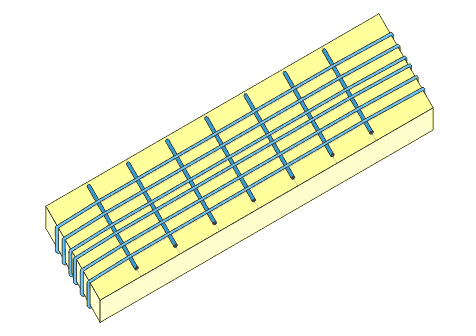
 Another method that I use regularly is shown in the drawing above. This method best represents round metal stanchions with wire rope as the railings. The jig for this method of soldering up railings is a lot easier to make. Once again I use a piece of MDF but this time there is no need to file long straight grooves only small grooves where the wire goes over the corner of the MDF to help keep things in place.
I start by drawing a plan of the railings onto the surface of the MDF. I usually make two pieces of railing at once, ie one for each side of the model hence the six rails in the diagram. File a small groove into the MDF at both ends of each drawn line. I then wrap thin copper wire around the jig so that it sits above the lines that have been drawn representing the railings. This wire needs to remain under a little tension so that all kinks etc are removed. I then cut larger diameter wire to be the stanchions. These are then slid under the rails one at a time and each one is soldered to the rails before inserting the next one. Starting from the center and working towards each end ensures that there is enough tension on the wires to hold things in place during soldering. Once again it will depend on how well you solder as to how much cleaning up is required in the end. When things have had a general clean up with a file, cut the ends of the rails to remove the assembly from the jig. Then cut the center of all the stanchions to separate the two lots of railings. There is a fair bit of waste wire with this method but you get a pretty good and consistent result.
