
Making a SPS-49 Radar for my Anzac Frigate is one of those jobs that I kept putting off because I just couldn’t work out a way of constructing it. Eventually I decided that I would solder one together from wire using a wooden block as a former. A very time consuming task but it has produced a reasonable looking radar.
Before I started construction I gathered enough information to be able to make a simple drawing at the appropriate size. The drawing in conjunction with several photos was enough to complete this model.
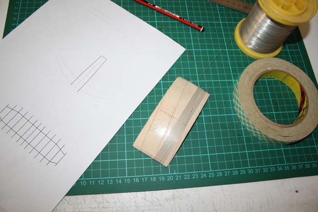 A wooden block a little bigger than the size of the radar was carved to shape to act as a former. The block was covered in double sided tape. 8 thou tinned copper wire was wrapped around the former to make the elements of the radar.
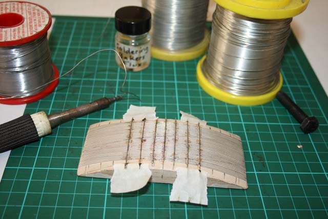 20 thou wire was then soldered to the elements to start forming the support frame. I found that I had to use tape to hold things in place during soldering. Plenty of flux was also required to help the solder run.
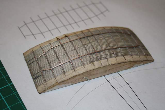 The first layer of the support frame was completed and the assembly was cleaned up with small needle files.
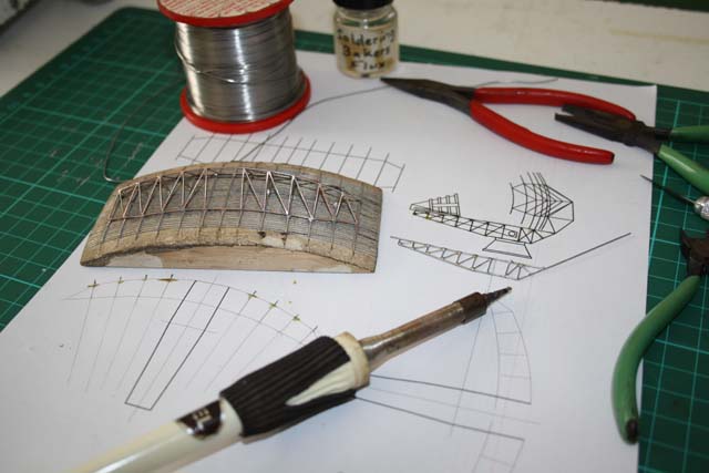 The rest of the support frame was built up with each piece being cut to size and soldered into place while holding it with a small pair of pliers.
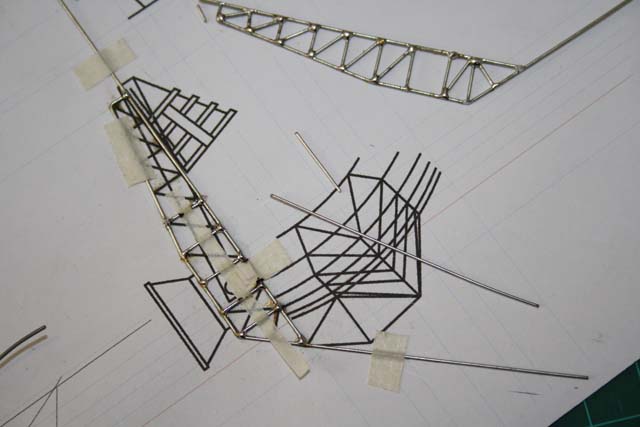 Laying the wire directly over the drawing and taping it down helped to ensure that everything lined up.
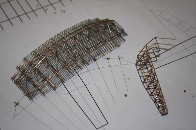 The main assembly was removed from the the forming block and trimmed to size. Getting the double sided tape to separate was a bit of a challenge and some minor damage was caused to some of the elements.
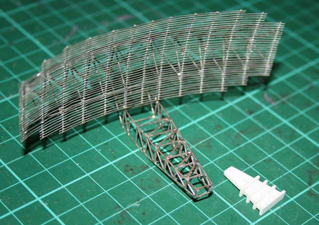 The two main assemblies soldered together.
.